
COD2 MODELING TUTORIAL
Author: MCh2207Cz
- This tutorial is not recommended for beginning COD2 modders cause it counts with basic COD2 file orientation of the
modder.
- A COD2 skinning and/or scripting experience is beneficial for better understanding this stuff.
- I recommend reading my "Skinning tutorial, Part 1" first.
Here you can read the tutorial as TXT file.
Note that in folder "SeeFiles" there is a lot of file stuff aimed for maximalize the example.
Note that in folder "SeeImages" there is located the whole image content
Note that in folder "EnclosedFiles" there are enclosed all (2) needed add-ons/plug-ins.
Topics covered:
(A) Tool list
(B) DDS converter "DDS to IWI" and IWI converter "IWI to DDS"
(C) WTV (Windows Texture Viewer)
(D) XmodelExporter
(E) Adobe Photoshop CS series
(F) Alias Maya 6.0
(G) Full described example of making a new weapon model
NOTE! All of processes described here requires a full installation of the Call Of Duty 2, you will need also where the game's files are situated in your computer - for example: C:\Program Files\Activision\Call Of Duty 2\
NOTE! For modeling purposes it is absolutely vital to have Maya 6.0.
NOTE! Due to various file operations it is highly recommended to enable drawing of the file
extension.
(A) Tool list
Firstly you will need this stuff...
1) Programs/applications:
----Alias Maya 6.0 (version 6.0 IS REQUIRED!)...REQUIRED PROGRAM
USE! Making the model itself.
----Editpad Lite...REQUIRED PROGRAM
DOWNLOAD:
http://www.editpadpro.com/editpadlite.html
USE! Scripting the files *.xmodel_export and making COD2 type material files.
NOTE! WITHOUT GOOD TEXT EDITOR/HEX EDITOR YOU WILL BE NOT ABLE TO MAKE
MODELS!
----XmodelExporter...REQUIRED PROGRAM
DOWNLOAD:
http://www.diegologic.net/CoD/XmodelExporter.htm
USE! Exporting COD2 type xmodels to format open able in Maya 6.0.
USE! Exporting skin files (DX7 - color maps and DX9 - normal, spectacular maps).
USE! Decoding tags (bones/joints).
USE! Reviewing the model itself without starting COD2.
NOTE! New versions of the program are appearing quite quickly, check the program's site for updates.
----Adobe Photoshop (CS series)...REQUIRED PROGRAM
USE! Making the skins for your models.
NOTE! I cannot speak for the new versions but version CS2 and lower DO NOT HAVE *.dds FORMAT AS DEFAULT OPENABLE FORMAT.
NOTE! SO APPLY THE DDS PLUGIN ENCLOSED TO THIS PACKAGE.
----WTV (Windows Texture Viewer)...RECOMMENDED PROGRAM
DOWNLOAD:
http://developer.nvidia.com/object/windows_texture_viewer.html
USE! Viewing the *.dds images much faster than via Adobe Photoshop.
USE! Alpha-blending view and separate channel view enabled.
----IWI converter "IWI to DDS"...REQUIRED PROGRAM
DOWNLOAD:
http://callofduty.filefront.com/file/IWI_to_DDS_Converter;52922
USE! Converting *.iwi images into *.dds images.
----DDS converter "DDS to IWI"...REQUIRED PROGRAM
DOWNLOAD:
http://callofduty.filefront.com/file/Image_to_IWI_Converter;51975
USE! Converting *.dds images into *.iwi images.
2) Add-ons, plug-ins:
----DDS PLUGIN FOR ADOBE PHOTOSHOP (CS series)...REQUIRED PLUGIN
ENCLOSED IN THIS PACKAGE - filename: "DDS_Plugin.zip"
USE! Saving ability into the *.dds format.
----COD2 MODELING EXPORTER...REQUIRED PLUGIN
ENCLOSED IN THIS PACKAGE - filename: "CODExportModelWindow.zip"
USE! Exporting the model to *.xmodel_export format.
NOTE! Use the enclosed exporter, cause the one that can be downloaded officially is somehow damaged, this one is corrected and WILL WORK.
NOTE! After installing Maya 6.0 you have to apply the COD2 exporter
NOTE! The exporter is behaving as a plug-in and in Maya there is a special way how to add plug-ins, the process will be described later.
----COD2 MODDING TOOLS...REQUIRED ADDON
DOWNLOAD:
http://callofduty.filefront.com/file/COD2_Updated_MapMod_Tools;61008
USE! Exporting the file *.xmodel_export files to the COD2 type xmodel and optionally making the COD2 type effect files.
NOTE! Install it via the installer. You will need these programs (found in folder "bin" in your default COD2 game path):
"Asset_manager.exe" - for exporting *.xmodel_export files to the COD2 type xmodel...VITAL USE
"COD2_EffectsEd.exe" - if you want to make your own effects (muzzle flash, shell eject)...OPTIONAL USE
----A LOT OF PATIENCE :-)
Install these programs before you start anything from this
tutorial...
----Alias Maya v6.0
----Editpad Lite
----Adobe Photoshop + DDS PLUGIN
----COD2 MODDING TOOLS
After installation, continue reading...
(B) DDS converter "DDS to IWI" and IWI converter "IWI to DDS"
DESCRIPTION:
A tool required to make *.dds and *iwi files for skinning.
INSTALLATION:
It is free software without installation - just drop it to a permanent folder (I do not recommend "Program files" because of the rewrite protection).
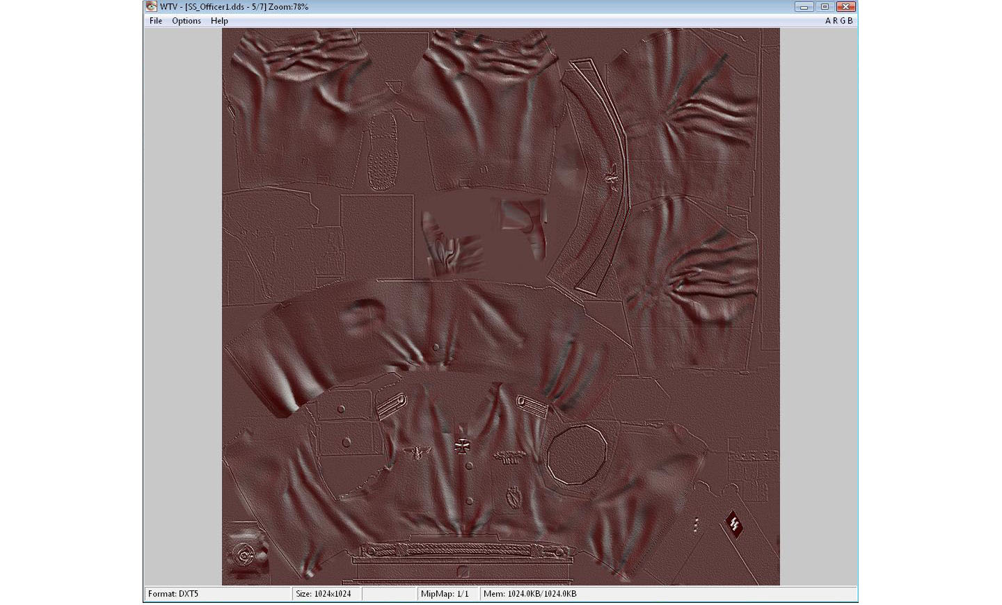
(C) WTV (Windows Texture Viewer)
DESCRIPTION:
It is an image viewer/browser that enables you to view all your *.dds files.
It also shows you the type of *.dds format the file is saved in.
INSTALLATION:
It is free software without installation - just drop it to a permanent folder (I do not recommend "Program files" because of the rewrite protection).
See image:
"WTV_01.gif"
DDS FILE FORMAT:
*.dds files have several formats (lots of them) - THE COD2 CAN USE ONLY THE DXT1 OR DXT5 FORMATS.
BECAUSE OF THE POSSIBLE COLISSIONS WITH THE DXT1 FORMAT I HIGHLY RECOMMEND TO USE DXT5 ONLY.
*.dds FILES CAN BE SAVED WITH SO CALLED "MIP-MAPS" - it is a filter that is applied when the model is far away from the player in the game.
If there is written for example this: "MipMap: 1/10"
It means that the image is saved with its maximum resolution chosen by creator and then when saving saved 10-times with 2-times smaller resolution than the image before.
See
image: "MipMap_01.gif"
IMPORTANT! IF YOU DO NOT WANT THE GAME TO RESIZE (it lowers the detail) YOUR SKIN, CHOOSE "NO MIPMAPS" WHILE SAVING TO *.dds FORMAT.
Use this as a default saving settings - See
image: "DDS_Saving_01.gif"
(D) XmodelExporter
DESCRIPTION:
XmodelExporter is a powerful utility that enables you to browse and convert particles of the all COD series xmodels (COD1, CODUO, COD2, COD4, COD5).
You can also freely view the models and you have a brief summary of features for each model listed in the program.
All models in COD2 are consisting of these parts which are also the names of the folders where you can find needed files in *.iwd archives.
I hope you have WinRar to open them, if not download it (http://www.rarlab.com) - it is free.
- xmodel
- xmodelsurfs
- xmodelparts
- materials
- images
xmodel is the file that makes the model together, it contains name of xmodelsurf, xmodelpart and material that belongs to the model.
xmodelsurfs is the model file itself.
xmodelparts contains essential tags (bones/joints) - it is a kind of a skeleton of the model.
materials are files that contain info about the skin files used and some rendering settings.
images are the skin files itself.
INSTALLATION AND STARTING UP:
The program does not require to be installed. Just drop it WITH ALL OTHER FILES FROM THE PACKAGE TO A PERMANENT FOLDER.
Then run the program called "IWI_X_DDS.exe" first.
Then run the XmodelExporter itself.
It is quite beneficial to read this stuff for basic knowledge:
- Readme file ("Readme.txt")
- Web site (http://www.diegologic.net/CoD/XmodelExporter.htm)
It is a very simple and fast program though (in the question of usage) so if you are lazy to study it try it yourself.
It is always better to discover things by heart.
See image:
"XmodelExporter_01.gif"
When running the XmodelExporter for the first time it will probably ask you for defining the default COD game folder. I think it is not absolutely necessary but I recommend doing so. Then define the working folder where the XmodelExporter will make a kind of "working environment". The program will make this directory structure:
- xmodel
- xmodelsurfs
- xmodelparts
- materials
- images
"xmodel" folder is folder where the program will search for xmodels.
"Refresh" buttons will update the list/properties.
"Settings" button sets the default COD game directories.
Xmodels are shown on the right in the list.
Particles (xmodelsurfs, xmodelparts, materials, images) of the xmodel are shown on the left.
"LOD distance" is the distance in game units (inches) from which the less detailed model will be used (if available of course).
See image:
"XmodelExporter_02.gif", "XmodelExporter_07.gif", "XmodelExporter_08.gif" and "XmodelExporter_09.gif"
"preview model" button starts the viewing mode for observing the model, on start-up the model is in the center and its skins are top right orientated.
"export" buttons export the model into .obj format (wavefront object) - a format open able in Maya 6.0.

See image:
"XmodelExporter_03.gif" and "XmodelExporter_06.gif"
"view tags" button starts the default internet browser to view the generated *.html file with tag (bone/joint) info.
See image:
"XmodelExporter_04.gif" and "XmodelExporter_05.gif"
"view image" button opens box with skin image.
NOTE! To be able to see the image rendered on the model you have to convert the
*.iwi files into *.dds in the same folder as the *.iwi and with the same name.
See image: "XmodelExporter_10.gif"
NOTE! If the converted *.dds image is white in the preview it means that it was converted into the *.dds format incompatible with XmodelExporter - to correct this issue export the *.iwi file with IWI converter "IWI to DDS", do not forget to rename it the same way as the IWI file.
XMODELEXPORTER AS A SKINNING UTILITY:
1) Take a shot of the polygon map (hit print screen on keyboard) - See
image: "XmodelExporter_09.gif"
2) Paste the screen into graphic editor (Adobe Photoshop).
3) Mark only the skin place and cut it into new file.
4) Resize it to a power of number 2 (2,4,8,16,32,64,128,256,512,1024,2048...).
WARNING do not exceed the size of 2048, some graphic cards do not support skins above 2048 pixels.
5) Save it.
6) You have now a map of a skin which parts are used - See
image: "MP40_Color_Map_01.jpg" and "MP40_Color_Map_With_Polygon_Map_01"
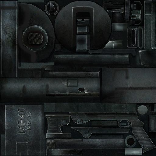

7) You can start skinning now much more accurately than before.
(E) Adobe Photoshop CS series
INSTALLATION OF THE PLUGIN:
1) Put file dds.8bi in directory ...\Adobe\Adobe Photoshop CS2\Plug-Ins\File Formats.
2) Put file mscrll.dll in directory ...\Adobe\Adobe Photoshop CS2.
Once installed, you are then able to open and save the *.dds files - See
image: "DDS_Format.gif"
DESCRIPTION:
Adobe Photoshop is a powerful graphic editor.
I will not describe the basic methods of working with Photoshop.
The internet is full of resources.
I will describe some characteristic techniques for COD2 modding.
ALPHA-BLENDING:
Make the "channels" box visible: Window -> Channels.
Click on the new channel and a new channel called "Alpha" will appear.
You can freely draw into this channel, but remember that it is a grayscale channel (8-bits) - so only black, white and shades of grey.
The black part of image will be 100% transparent, the white part of image will be 100% visible (so non-transparent) and the shades of grey something between these two.
Rules:
- Black - transparent
- White - visible
- Shades of grey - semi-transparent (the more darker the alpha is the more transparent the image is).
See image:
"Alpha_Blend_01.gif" and "Alpha_Blend_Example_01.gif"
Usage:
1) Alpha-blend is used on a special type of COD2 skins (examples - mg42, pps42, svt40, 30cal).
It makes some parts of the image transparent (mg42 - barrel cover, pps42 - barrel cover, svt40 - muzzle break and forearm, 30cal - barrel cover).
2) Alpha-blend is used as well as in almost all COD2 icons and for example also on reticles (snipers, binoculars)
See image:
"StenIcon_Alpha_01.jpg" and "Sten_Icon_RGB_01.jpg"
![]()
![]()
3) Alpha-blend is used also for DX9 mode of the game.
The model is rendered with a texture (or skin if you want) - but it is not the only one image applied on model.
The skin is in COD2 called "color map".
The other two (that are enabled only in DX9 mode) are: "spectacular map" and "normal map".
The spectacular map makes the model shine in the sun and the normal map makes the 3D "plastic" effect.
All 3 maps are images. The spectacular and normal maps contain the alpha-blend to highlight the effect.
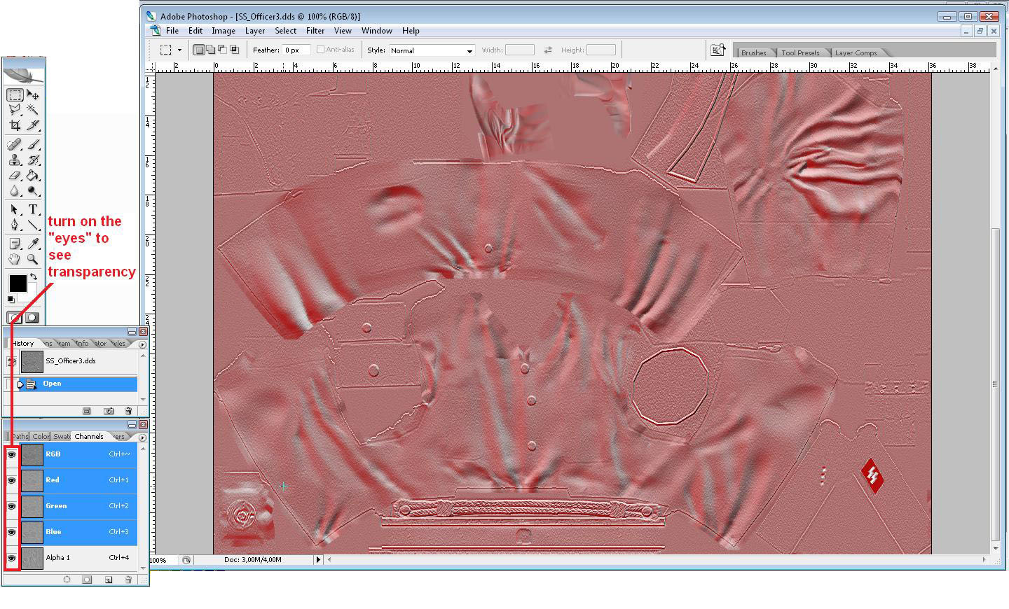
NORMAL map is the image that contains both the RGB channel and ALPHA.
Normal map is in grayscale (recommended).
The 3D effect is simulated by the contrast between colors on this map.
Using WTV program you can turn transparency on (by hitting key "A").
It is also possible in Adobe Photoshop to turn on the visibility of the all 4 channels (click on the "eyes" on the left of channel).
I personally use this filter to simulate normal maps: Filter -> Stylize -> Emboss
See image:
"Normal_Map_View_In_WTV_01.jpg" and "Normal_Map_View_In_Photoshop_01.jpg"
SPECTACULAR maps are defining which parts of the color map skin should shine and the level of it.
Generally I can say that by adding color to the RGB you can adjust the color tone of the shine.
Also the lighter the image is the shinier the skin will look.
It is quite a long journey though until you "get it under the skin".
It takes a while before you can guess the color light and the other stuff to make the skin look like how you want it.
I personally use this filter to simulate spectacular maps: Image -> Adjustments -> Shadow/Highlight
MAKING DX9 MAPS (NORMAL AND SPECTACULAR):
1) Once you have finished your skin (color map) save it somewhere 3 times.
(As 3 separate files all in *.dds or to keep the quality in *.tga - both can have alpha)
When saving to *.tga make sure the tick for alpha channel is on - See
image: "Storing_Skins_02.jpg"
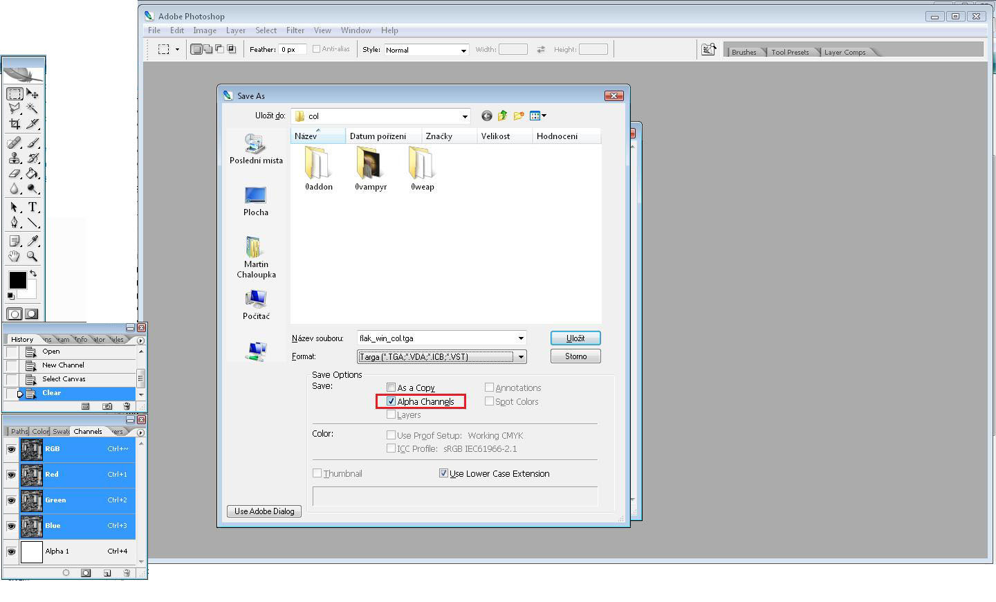
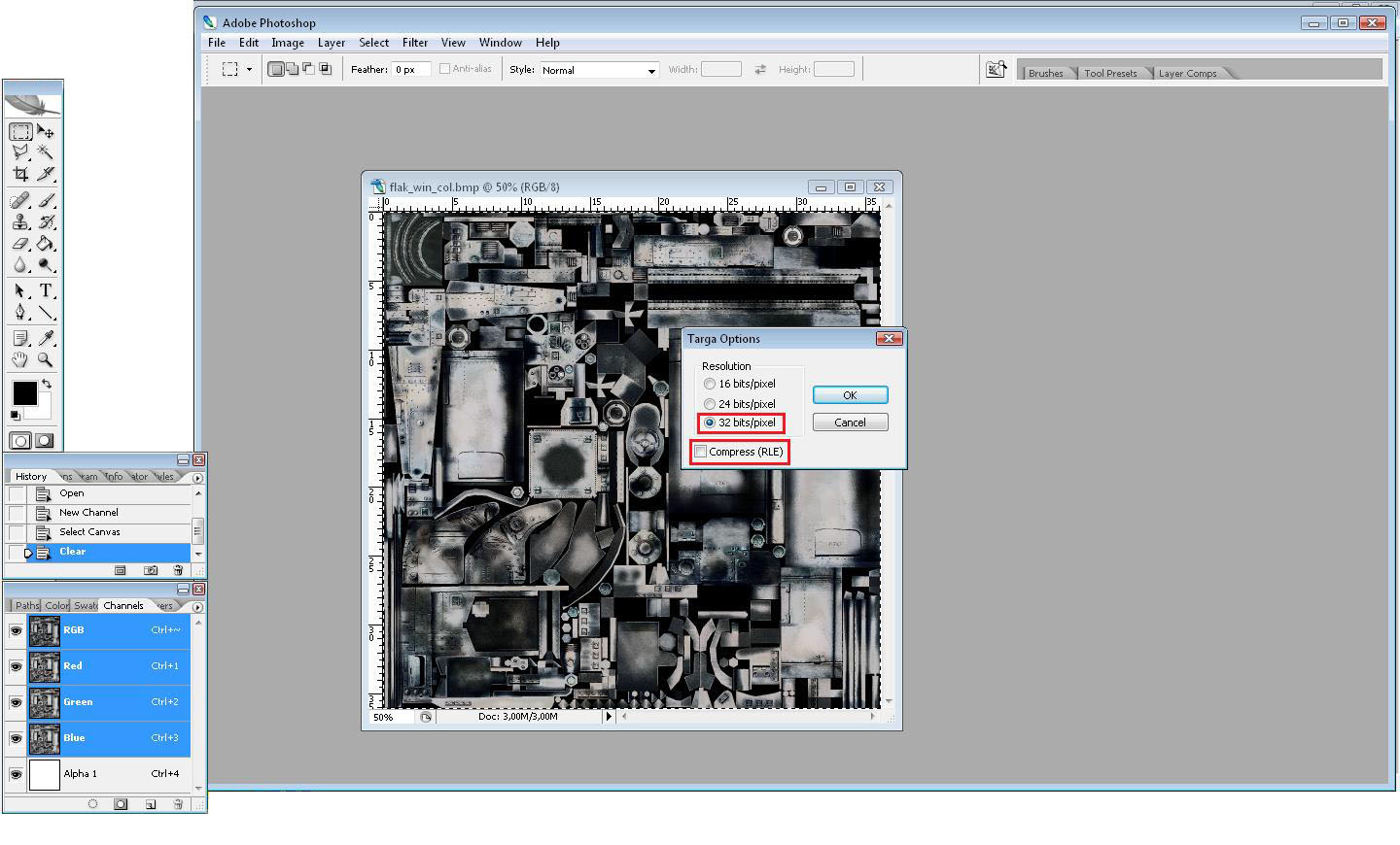
Then tick 32-bit and DO NOT tick the compression - See image: "Storing_Skins_01.jpg"
2) Name it this way not to be lost then:
"nameofskin_col"
"nameofskin_norm"
"nameofskin_spec"
3) col = color map...finished, leave it as it is, skin/texture file.
norm = normal map...we will work with it.
spec = spectacular map...we will work with it.
4) All of these files are now the same, the color map is finished so we will leave it.
5) Open the "nameofskin_norm" file.
6) Select all, copy, paste - you have 2 layers.
Click on one layer and apply the "emboss" filter (Filter -> Stylize -> Emboss).
Emboss settings - height: 2 pixels; amount: 100%; angle: circa 45°or -45° or 135° or -135°, click "OK".
Then select the second layer and apply "emboss" filter
Emboss settings - height: 2 pixels; amount: 100%; angle: circa 0°or 180° or 90° or 270°, click "OK".
7) The layer that was "embossed" by circa 0°or 180° or 90° or 270° is for alpha channel.
8) The layer that was "embossed" by circa 45°or -45° or 135° or -135° is for RGB channel.
9) While everything on position save it and quit the file.
10) Open the "nameofskin_spec" file.
11) Select all, copy, paste - you have 2 layers.
Click on one layer and apply "Shadow/Highlight" (Image -> Adjustments -> Shadow/Highlight).
This has no strict rule, make it light/dark as you think it should be.
The RGB and ALPHA can be the same but alpha is better to be contrasted and a bit lighter with highlighted edges.
12) When you have the RGB and Alpha finished save it and quit the file.
13) If you have saved the files in *.dds you are ready to convert them using DDS converter "DDS to IWI".
If you have saved the files for storage purposes as *.tga you have to save them as *.dds and then convert.
ALWAYS REMEMBER THAT IF YOU WANT TO KEEP YOUR OWN SKINS IT IS BETTER TO SAVE THEM AS "TGA" CAUSE IT HAS NO LOST OF QUALITY.
Well I must admit it took me quite a very long time until I realized how to (effectively) create these maps.
It needs time to handle...(and patience).
(F) Alias Maya 6.0
FOR COD2 MODELING PURPOSES IT IS ABSOLUTELY VITAL TO HAVE THE MAYA VERSION 6.0.
THE COD2 MODELING TOOLBAR IS BUILT JUST FOR THIS VERSION.
Note! I will describe here only the ways of adjusting the existing models (exported from stock COD2 game) cause it is much simpler than making new ones.
Note! I will make a look especially on the weapons.
INSTALLING THE COD2 MODELING TOOLBAR FOR MAYA:
3 conditions have to be fulfilled:
- full installation of the COD2
- COD2 modding tools installed
- Maya 6.0 installed
1) After installing Maya 6.0 a new folder "Maya" has appeared in your "My documents" directory (the document's directory on the desktop).
2) In this "Maya" folder there should be 3 subfolders: "6.0", "projects", "scripts" and a "MayaLog" file.
3) Open the "6.0" folder.
4) In the "6.0" folder there are 3 more subfolders: "Prefs", "Presets", "Scripts" and a "Maya.env" file.
5) Open the "scripts" folder.
6) You have to copy here the file that is situated here: "your Call Of Duty 2 default game path\Bin\Maya\Scripts" -
See image:
"Bin_Maya_Folder_01.gif"
The filename should be "Usersetup.mel"
By "your Call Of Duty 2 default game path" I mean the EXACT directory path of your Call Of Duty 2 installation - the path that is offered in the COD2 installation program is I think "C:\Program Files\Activision\Call Of Duty 2\" but if you have changed it you have to write it changed.
7) Return upwards in the directory tree to the folder "6.0"
8) Open "Maya.env" file with the Editpad Lite (I told you on the beginning of the tutorial that we will need a text editor).
When opened the "Maya.env" file should be blank (nothing written in it).
9) Add these lines into the "Maya.env" file:
MAYA_PLUG_IN_PATH = your Call Of Duty 2 default game path\Bin\Maya
MAYA_SCRIPT_PATH = your Call Of Duty 2 default game path\Bin\Maya
10) Save "Maya.env" file and close it.
11) Close the "6.0" folder.
12) Go to this directory: "your Call Of Duty 2 default game path\Bin\Maya" - See
image: "Bin_Folder_01.gif" and "Bin_Maya_Folder_01.gif"
13) You see the file "CODExportModelWindow.mel" with date of adjustment 13.2.2006 18:43
14) REWRITE this file with the one situated in "CODExportModelWindow.zip" (enclosed to this tutorial)
So the date of adjustment will be 29.4.2006 21:47
15) Close the "Maya" folder.
16) Now start Maya 6.0.
If you have done everything rightly you will see a COD2 toolbar on the top right -
See image:
"Maya_COD2_Toolbar_01.gif"
MAYA TOOLBARS:
Open Maya 6.0.
Now you see the interface - See
image: "Maya_COD2_Interface_01.gif"
Before you start doing anything watch the learning videos (Help -> Learning Movies...).
These movies contain the very basic skills needed in the modeling process.
To watch them you need QuickTime player, if you do not have it click the "download" button and then install it.
Now to the interface:
AXISES:
The X-axis is RED.
The Y-axis is GREEN.
The Z-axis is BLUE.
Axonometric plane is marked YELLOW (axonometric plane is the plane that is created from the current view).
If you select one of the axes on tools it becomes yellow.
VIEWS:
There are several predefined views (bookmarks):
- top x bottom
- front x back
- right side x left side
- perspective
You can choose them: View -> Predefined Bookmarks.
See image:
"Maya_Predefined_Views_01.gif" and "Maya_Predefined_Views_02.gif"

The perspective view is quite inaccurate for editing purposes, it is used mostly for evaluation and overview and of course for better 3D imagination.
To move the view hold: ALT + mouse middle button + mouse movement
To rotate the view hold: ALT + mouse left button + mouse movement
To zoom the view hold: ALT + mouse right button + mouse movement
or
To zoom the view scroll: mouse wheel up/down
BASIC TOOLS:
Select tool - selects object group after clicking
Lasso tool - selects object group after encircling in lasso
By hitting "DELETE" you will erase the selected object
Move tool - moves the selected object by the one selected axis or by the axonometric plane.
Rotate tool - rotates the selected object by the one selected axis or by the axonometric plane.
Scale tool - scales the selected object by the one selected axis or by the axonometric plane.
When you hit the "INSERT" key you can change the pivot of the movement/rotation/scaling, hit again to return.
Soft modification tool - enables you to make more detailed adjustment to the model than using movement/rotation/scaling.
When selected this tool click on the place you want the pivot of the changes.
The object will get purple color and a special tool will appear - See
image: "Maya_Soft_Mod_01.gif"
You can also modify not only the whole object group but also its parts called faces.
Select object, click on it right mouse and hold it - a new box of buttons will appear, apply the "faces".
See image:
"Maya_Faces_01.gif"

You can do the same basic operations as with groups here (movement/rotation/scaling/soft modification).
WEAPON MODELING:
Models converted with XmodelExporter are 2.5-times smaller than the real COD2 models. So before you do anything you have to rescale them by 2.5x
You will do it this way - select the group, on the right a box with options will appear, click on "group#" and under "Transform attributes" there is "Scale" with 3 numbers (all are number "1.000"), rewrite these three ones into "2.500"
See image:
"Maya_Resize_01.gif" and "Maya_Resize_02.gif"

When you want to create your own weapon from the stock one, you have to know which stock COD2 weapon will be the basic one.
When creating the new weapon you have to make 2 separate models - viewmodel (player's weapon) and the weapon (worldmodel, AI's weapon, dropped weapons).
The viewmodel is divided into several groups, the worldmodel is only one group.
Each group in the model file has to be named in a strict exact way and has its exact position.
The position is captured in models converted with XmodelExporter - each group is right at place so it is without work.
The worse thing is with the names, you have to name them exactly due to the game's animations.
You can find all the needed names in the XmodelExporter by viewing the tags - See
image: "XmodelExporter_06.gif" and "XmodelExporter_03.gif"
You have to know the difference between these names cause some of the names are names of groups and some are names of points in space.
Generally we can say that point's names begin with "tag_" (tag_flash, tag_brass, tag_origin).
The other names are mostly group's names (j_gun, j_clip, j_bolt...) - NOTE! One exception to the rule - "tag_weapon" is the name of the worldmodels group.
See image:
"Maya_Rename_01.gif" and "Maya_Group_Name_01.gif" and "Maya_Joint_Name_01.gif"
See image:
"Names_BrenGun_01.gif"
"Names_GreaseGun_01.gif"

"Names_kar98k_01.gif"

"Names_Shotgun_01.gif"
"Names_Thompson_01.gif"
"Names_Webley_01.gif"
VIEWMODELS CAN CONTAIN THESE (and more others, but these are the most common ones):
1) group names
| j_gun | general group name, all viewmodels should have it, we can say it is weapon's body (held in hands) |
| j_clip | general group name, magazine-fed weapons, applied when reloading |
| j_bolt | general group name, weapon's bolt, applied when firing (the thing that is moving when shooting) |
| j_stripper | bolt-action rifle group name, bolt-action rifles reloaded by stripper clips (unscoped - kar98k, mosin, garand, lee-enfields) |
| j_round | bolt-action rifle group name, bolt-action rifles reloaded round by round (snipers - kar98k, mosin, springfield) |
| j_shutter | grease-gun shell eject cover |
| j_handle | brengun group name, barrel handle |
| j_bipod | brengun group name, bipod |
| gun_pivot | webley group name, pivot of the gun, applied when reloading |
| j_quickloader | webley group name, reloading stripper without ammo, applied when reloading |
| j_trigger | webley group name, trigger |
| j_quickloader_bullets | webley group name, live ammo from the reloading stripper, applied when reloading |
| j_chamber | webley group name, chamber (rounded thing which is filled with ammo) |
| j_bullet1 | webley group name, fired round case, applied when reloading |
| j_bullet2 | webley group name, fired round case, applied when reloading |
| j_bullet3 | webley group name, fired round case, applied when reloading |
| j_bullet4 | webley group name, fired round case, applied when reloading |
| j_bullet5 | webley group name, fired round case, applied when reloading |
| j_bullet6 | webley group name, fired round case, applied when reloading |
| j_hammer | shorgun group name, hammer, applied when firing |
| j_pump | shotgun group name, forearm pump, applied when firing |
| j_clip_pin | grenade group name, the safety catch |
2) joint names
| tag_origin | general joint name, viewmodels can have it |
| tag_flash | general joint name, all viewmodels should have it, defines where the muzzle flash will appear |
| tag_brass | general joint name, all viewmodels should have it, defines where the shell eject will appear |
WORLDMODELS CAN CONTAIN THESE (and more others, but these are the most common ones):
1) group name (the only one)
| tag_weapon | general group name, worldmodel has to contain this to function properly |
2) joint names
| tag_origin | general joint name, all worldmodels must have it |
| tag_flash | general joint name, all worldmodels must have it, defines where the muzzle flash will appear |
| tag_brass | general joint name, all worldmodels must have it, defines where the shell eject will appear |
| pistolgrip | handgun specific joint name, all pistol worldmodels must have it |
(G) Full described example of making a new weapon model
We will make a Thompson based model, cause it is one of simpliest models.
1) I hope you have WinRar, if not download it (http://www.rarlab.com), install it and then continue reading.
2) Browse to you COD2 default game folder and open the directory "Main" where are all *.iwd files stored.
3) These *.iwd files contain all data the game needs for running.
4) Double click the file "iw_13.iwd", select to find the program in list and select WinRar to open it, open as well the file "iw_14.iwd".
5) In the file "iw_13.iwd" open "xmodel" folder.
6) In "xmodel" folder find these 2 files: "weapon_thompson" and "viewmodel_thompson"
7) Copy these files into "xmodel" folder in the active directory of the XmodelExporter.
8) In the file "iw_13.iwd" in folder "xmodel" select "viewmodel_thompson" and hit keys ALT + V, a new window will appear and there are written some things, do the same with "weapon_thompson".
9) You have to find here names of the other files needed - See
image: "WinRar_Iwd_01.gif" and "WinRar_Iwd_02.gif"
10) So we know that we have to find these:
xmodelparts "weapon_thompson_high1" and "viewmodel_thompson2",
xmodelsurfs "weapon_thompson_high1", "weapon_thompson_med1", "weapon_thompson_low1" and "viewmodel_thompson2",
material "mtl_weapon_thompson"
11) In the file "iw_13.iwd" open "xmodelparts" folder.
12) In the "xmodelparts" folder find these 2 files: "weapon_thompson_high1" and "viewmodel_thompson2".
13) Copy these files into "xmodelparts" folder in the active directory of the XmodelExporter.
14) In the file "iw_14.iwd" open "xmodelsurfs" folder.
15) In the "xmodelsurfs" folder find these 4 files: "weapon_thompson_high1", "weapon_thompson_med1", "weapon_thompson_low1" and "viewmodel_thompson2".
16) Copy these files into "xmodelsurfs" folder in the active directory of the XmodelExporter.
17) In the file "iw_13.iwd" open "materials" folder.
18) In the "materials" folder find file "mtl_weapon_thompson"
19) Copy this file into "materials" folder in the active directory of the XmodelExporter.
20) In the file "iw_13.iwd" in folder "materials" select "mtl_weapon_thompson" and hit keys ALT + V, a new window will appear and there are written some things.
21) You have to find here names of the other files needed - See
image: "WinRar_Iwd_03.gif"
22) So we know that we have to find these:
images "weapon_thompson_c.iwi", "~weapon_thompson_n-gggr.iwi", "~weapon_thompson_s-rgb&weapon_thompson_cp-l-11.iwi"
23) In the COD2 "Main" directory in the iw_08.iwd up to iw_13.iwd in folder "images" you have to find these 3 image files and copy them into "images" folder in the active directory of the XmodelExporter.
24) Now you are ready to start the XmodelExporter so start it.
25) You should see this - See
image: "XmodelExporter_Thompson_01.gif"

26) Select "viewmodel_thompson" and click on the "viewmodel_thompson2" under "Surfaces" and click "Export .Obj" -
See image:
"XmodelExporter_Thompson_02.gif"
27) Select "weapon_thompson" and click on the "weapon_thompson_high1" under "Surfaces" and click "Export .Obj" -
See image:
"XmodelExporter_Thompson_03.gif"
28) Now open the active directory of the XmodelExporter, you find the address here -
See image:
"XmodelExporter_Thompson_04.gif"
29) Open subfolder "Obj".
30) Double click the files "weapon_thompson_high1.obj" and "viewmodel_thompson2.obj".
31) Select to find the needed program in the list and select Maya to open.
32) Maya will be opened twice - one with the "weapon_thompson_high1.obj" and one with the "viewmodel_thompson2.obj".
33) Select the Maya window with "weapon_thompson_high1.obj".
34) Resize the group by 2.5x - See
image: "Maya_Resize_01.gif" and "Maya_Resize_02.gif"
35) Make changes to the model you want.
36) Rename the group to "tag_weapon" - See
image: "Maya_Rename_01.gif"
37) Make joints for flash and shell eject - switch Maya into an "Animation" mode and under "Skeleton" select "Joint tool" -
See image:
"Maya_Thompson_01.gif"
38) Click with joint tool somewhere around the muzzle and somewhere around the ejector, rename the joints ("tag_flash", "tag_brass") -
See image:
"Maya_Thompson_02.gif"
39) Click "File" and "Save scene as" (File -> Save scene as), write the filename for example "mythompson_world.mb".
40) Save it for example into "My documents" or where you want, the file format must be *.mb (Maya binary).
41) When saved click "COD Tools" and "Model exporter" (COD Tools -> Model Exporter).
42) Click "Add new entry".
43) Put the tick in "Entry1".
44) Click "..." and select your previously saved *.mb file.
45) Click "Set".
46) Click "Yes".
47) Select the whole model (Edit -> Select all)
48) Click "Export all entries".
49) If no error occurs. Look in the "My documents" and a new file should appear (*.xmodel_export file), if you saved your *.mb file elsewhere the *.xmodel_export file will be right where the *.mb file is.
50) Select the Maya window with "viewmodel_thompson2.obj".
51) Resize the groups by 2.5x.
52) Make changes to the model you want.
53) Rename the groups as they should be ("j_gun" for gun base, "j_clip" for magazine and "j_bolt" for breech) -
See image:
"Names_Thompson_01.gif"
54) Make joints for flash and shell eject ("tag_flash", "tag_brass").
55) Click "File" and "Save scene as" (File -> Save scene as), write the filename for example "mythompson_view.mb".
56) Save it for example into "My documents" or where you want, the file format must be *.mb (Maya binary).
57) When saved click "COD Tools" and "Model exporter" (COD Tools -> Model Exporter).
58) Click "Add new entry".
59) Put the tick in "Entry1".
60) Click "..." and select your previously saved *.mb file.
61) Click "Set".
62) Click "Yes".
63) Select the whole model (Edit -> Select all)
64) Click "Export all entries".
65) If no error occurs. Look in the "My documents" and a new file should appear (*.xmodel_export file), if you saved your *.mb file elsewhere the *.xmodel_export file will be right where the *.mb file is.
Note! If you experience some errors, they are in the most cases because of double names (name mismatch), if so Maya will switch you to the object that has wrong name - so rename it and try exporting once more. There can be several name mismatches.
66)
In case you named the *.mb files "mythompson_world.mb" and "mythompson_view.mb", the *.xmodel_export file will be:
"mythompson_world.mb.xmodel_export"
"mythompson_view.mb.xmodel_export"
67) The *.xmodel_export files have name always same as the *.mb files plus the ".xmodel_export" extension.
68) Make copies of both *.xmodel_export files and rename the copies this way:
"mythompson_world.xmodel_export"
"mythompson_view.xmodel_export"
69) Open both copies with Editpad Lite (I told you we will need it).
70) You will see this: "EditpadLite_Thompson_01.gif"
71) Now it is a little bit complicated so read carefully.
72) The *.xmodel_export files have its own strict structure that has to be respected. I will describe the needed knowledge on opened file "mythompson_world.xmodel_export".
"mythompson_world.xmodel_export" - See
image: "EditpadLite_Thompson_01.gif" and "EditpadLite_Thompson_02.gif":
The first 3 lines begin with "//" - let as they are, we are not interested in these.
4th line: "MODEL"
5th line: "VERSION 6"
Leave it as it is.
6th line is blank.
7th line: "NUMBONES 4"
NUMBONES means number of bones, bones are names of joints and names of groups together
8th line: "BONE 0 -1 "tag_brass"
9th line: "BONE 1 -1 "tag_flash"
10th line: "BONE 2 -1 "tag_origin"
11th line: "BONE 3 -1 "tag_weapon"
"tag_brass", "tag_flash" and "tag_origin" are joints (names of joints).
"tag_weapon" is group (name of group).
When we were making worldmodel of our thompson we named its (only one) model group as "tag_weapon" - so it is name of group.
When we were making worldmodel of our thompson we named its 3 joints we made as "tag_brass", "tag_flash" and "tag_origin" - so these are names of joints.
The order of these BONEs is absolutely important as well as their numbers (you will realize the reason later).
12th line is blank.
13th line: "BONE 0"
14th line: "OFFSET -5.612528, 0.000000, 0.740413"
15th line: "SCALE 1.000000, 1.000000, 1.000000"
16th line: "X 1.000000, 0.000000, 0.000000"
17th line: "Y 0.000000, 1.000000, 0.000000"
18th line: "Z 0.000000, 0.000000, 1.000000"
"BONE 0" means that we will define BONE 0 (so "tag_brass").
"OFFSET -5.612528, 0.000000, 0.740413" means coordinates of the "BONE 0" in x, y, z order (x=-5.612528, y=0.000000, z=0.740413).
"SCALE 1.000000, 1.000000, 1.000000" means scaling of the "BONE 1" in x, y, z order (x=1.000000, y=1.000000, z=1.000000).
"X 1.000000, 0.000000, 0.000000" means rotation of the "BONE 0", "X 1.000000, 0.000000, 0.000000" is a normal vector for plane yz.
"Y 0.000000, 1.000000, 0.000000" means rotation of the "BONE 0", "Y 0.000000, 1.000000, 0.000000" is a normal vector for plane xz.
"Z 0.000000, 0.000000, 1.000000" means rotation of the "BONE 0", "Z 0.000000, 0.000000, 1.000000" is a normal vector for plane xy.
Leave the values of the rotation always on these normal vector values.
19th line is blank.
20th - 39th line defines bones "BONE 1", "BONE 2", "BONE 3".
40th line is blank.
41st line: "NUMVERTS 1246"
"NUMVERTS 1246" means that number of vertices is 1246, so definition of vertices will follow.
42nd line: "VERT 0"
"VERT 0" means that vertice number 0 will be defined.
43rd line: "OFFSET 9.075925, 0.084737, 0.896626" means coordinates of the "VERT 0" in x, y, z order (x=9.075925, y=0.084737, z=0.896626)
44th line: "BONES 1" means number of bones that belong to the "VERT 0"
45th line: "BONE 3 1.000000" means which bone belongs to the "VERT 0"
46th line is blank.
47th - 6270th line defines vertices 1 - 1245.
6271st line is blank
6272nd line: "NUMFACES 951"
"NUMFACES 951" means that number of faces is 951, so definition of faces will follow.
6273rd line: "TRI 0 0 0 0"
To be honest I do not know what that means.
6274th line: "VERT 0" means that definition belongs to the vertice number 0.
6275th line: "NORMAL 1.000000 0.000000 0.000000"
To be honest I do not know what that means.
6276th line: "COLOR -1.000000 -1.000000 -1.000000 -1.000000"
To be honest I do not know what that means.
6277th line: "UV 1 0.083179 0.842113"
To be honest I do not know what that means.
6278th - 18635th line defines faces for vertices 1 - 1245.
18636th line is blank.
18637th line: "NUMOBJECTS 1" means number of objects.
18638th line: "OBJECT 0 "tag_weaponShape"" defines object number 0 called "tag_weaponShape".
The object's name is the same as the name of the group plus the word "Shape" ("tag_weapon" + "Shape" = "tag_weaponShape").
To be honest it really does not matter what name you write here, but you have to write some name.
18639th line is blank.
18640th line: "NUMMATERIALS 1" means that number of materials is 1.
18641st line: "MATERIAL 0 "mtl_weapon_thompson1" "Phong" "weapon_thompson_c.dds""
18642nd line: "COLOR 0.000000 0.000000 0.000000 1.000000"
18643rd line: "TRANSPARENCY 0.000000 0.000000 0.000000 1.000000"
18644th line: "AMBIENTCOLOR 0.000000 0.000000 0.000000 1.000000"
18645th line: "INCANDESCENCE 0.000000 0.000000 0.000000 1.000000"
18646th line: "COEFFS 0.800000 0.000000"
18647th line: "GLOW 0.000000 0"
18648th line: "REFRACTIVE 6 1.000000"
18649th line: "SPECULARCOLOR 0.300000 0.300000 0.300000 1.000000"
18650th line: "REFLECTIVECOLOR 0.000000 0.000000 0.000000 1.000000"
18651st line: "REFLECTIVE 1 0.500000"
18652nd line: "BLINN -1.000000 -1.000000"
18653rd line: "PHONG 2.060000"
"MATERIAL 0" means that material number 0 will be defined.
"mtl_weapon_thompson1" is the name of material file for the material number 0 (so for the object number 0).
"Phong" is type of material.
"weapon_thompson_c.dds" is the name of skin file that should be contained in the "mtl_weapon_thompson1".
Lines 18642 to 18653 define some (?) material features.
18654th line is blank.
18655th line is blank.
73) We will be adjusting lines 7 - 39 and 18637 - 18653.
74) Now we have to redefine bones (tags).
75) Run XmodelExporter.
76) Select "weapon_thompson" and view its tags.
77) A Internet browser should be initiated with something like this inside:
tag# name (X, Y, Z), parent
# 0 = tag_weapon , (0.00, 0.00, 0.00)
# 1 = tag_brass , (-5.77, -0.84, 1.24), parent = #0, angles = (-20.61, 10.59, -20.61)
# 2 = tag_flash , (9.91, 0.01, 1.59), parent = #0
__ tag_weapon
|___ tag_brass
|___ tag_flash
See image:
"XmodelExporter_Thompson_05.gif"
78) Now you see that the "tag_weapon" bone should be the main (in COD2 called parent) bone.
79) In the stock COD2 thompson model there are only 3 bones, we will add one more - "tag_origin" (it is the most basic tag for all models).
80) Our structure should look like this:
__ tag_origin joint parent: no
|__ tag_weapon group parent: "tag_origin"
|___ tag_brass joint parent: "tag_weapon"
|___ tag_flash joint parent: "tag_weapon"
81) Open the "mythompson_world.xmodel_export". Go to line 7 - 39. We have to change this (see - "mythompson_world_step1.XMODEL_EXPORT"):
NUMBONES 4
BONE 0 -1 "tag_brass"
BONE 1 -1 "tag_flash"
BONE 2 -1 "tag_origin"
BONE 3 -1 "tag_weapon"
BONE 0
OFFSET -5.612528, 0.000000, 0.740413
SCALE 1.000000, 1.000000, 1.000000
X 1.000000, 0.000000, 0.000000
Y 0.000000, 1.000000, 0.000000
Z 0.000000, 0.000000, 1.000000
BONE 1
OFFSET 11.599256, 0.000000, 1.372895
SCALE 1.000000, 1.000000, 1.000000
X 1.000000, 0.000000, 0.000000
Y 0.000000, 1.000000, 0.000000
Z 0.000000, 0.000000, 1.000000
BONE 2
OFFSET 0.000000, 0.000000, 0.000000
SCALE 1.000000, 1.000000, 1.000000
X 1.000000, 0.000000, 0.000000
Y 0.000000, 1.000000, 0.000000
Z 0.000000, 0.000000, 1.000000
BONE 3
OFFSET 0.000000, 0.000000, 0.000000
SCALE 2.500000, 2.500000, 2.500000
X 1.000000, 0.000000, 0.000000
Y 0.000000, 1.000000, 0.000000
Z 0.000000, 0.000000, 1.000000
82) Into this (see - "mythompson_world_step2.XMODEL_EXPORT"):
NUMBONES 4
BONE 0 -1 "tag_origin"
BONE 1 0 "tag_weapon"
BONE 2 1 "tag_brass"
BONE 3 1 "tag_flash"
BONE 0
OFFSET 0.000000, 0.000000, 0.000000
SCALE 1.000000, 1.000000, 1.000000
X 1.000000, 0.000000, 0.000000
Y 0.000000, 1.000000, 0.000000
Z 0.000000, 0.000000, 1.000000
BONE 1
OFFSET 0.000000, 0.000000, 0.000000
SCALE 2.500000, 2.500000, 2.500000
X 1.000000, 0.000000, 0.000000
Y 0.000000, 1.000000, 0.000000
Z 0.000000, 0.000000, 1.000000
BONE 2
OFFSET -5.612528, 0.000000, 0.740413
SCALE 1.000000, 1.000000, 1.000000
X 1.000000, 0.000000, 0.000000
Y 0.000000, 1.000000, 0.000000
Z 0.000000, 0.000000, 1.000000
BONE 3
OFFSET 11.599256, 0.000000, 1.372895
SCALE 1.000000, 1.000000, 1.000000
X 1.000000, 0.000000, 0.000000
Y 0.000000, 1.000000, 0.000000
Z 0.000000, 0.000000, 1.000000
83) Reasons for step 81) and 82):
According to step 80) the "tag_origin" has to be on the 1st place - so BONE 0 with number "-1". The "tag_weapon" is dependant on BONE 0 - so "tag_weapon" is BONE 1 with number "0" ("0" for BONE 0). The "tag_brass" is dependant on BONE 1 - so "tag_brass" is BONE 2 with number "1" ("1" for BONE 1). The "tag_flash" is dependant on BONE 1 - so "tag_flash" is BONE 3 with number "1" ("1" for BONE 1).
Now you have the order, you have to also reorder the bone definitions.
"tag_origin" is joint so scale is "1", offset is "0" and rotation is default:
BONE 0
OFFSET 0.000000, 0.000000, 0.000000
SCALE 1.000000, 1.000000, 1.000000
X 1.000000, 0.000000, 0.000000
Y 0.000000, 1.000000, 0.000000
Z 0.000000, 0.000000, 1.000000
"tag_weapon" is group so scale is "2.5" (I told you that *.obj is 2.5 times smaller), offset is "0" and roation is default:
BONE 1
OFFSET 0.000000, 0.000000, 0.000000
SCALE 2.500000, 2.500000, 2.500000
X 1.000000, 0.000000, 0.000000
Y 0.000000, 1.000000, 0.000000
Z 0.000000, 0.000000, 1.000000
"tag_brass" is joint so scale is "1", offset has to be copied exactly like it was (it defines place where the shelleject will appear, you can easily differ the flash and brass definition by fact that brass definition has almost always smaller number on "x" value) and rotation is default:
BONE 2
OFFSET -5.612528, 0.000000, 0.740413
SCALE 1.000000, 1.000000, 1.000000
X 1.000000, 0.000000, 0.000000
Y 0.000000, 1.000000, 0.000000
Z 0.000000, 0.000000, 1.000000
"tag_flash" is joint so scale is "1", offset has to be copied exactly like it was (it defines place where the muzzle flash will appear, you can easily differ the flash and brass definition by fact that flash definition has almost always larger number on "x" value) and rotation is default:
BONE 3
OFFSET 11.599256, 0.000000, 1.372895
SCALE 1.000000, 1.000000, 1.000000
X 1.000000, 0.000000, 0.000000
Y 0.000000, 1.000000, 0.000000
Z 0.000000, 0.000000, 1.000000
84) Now jump into line 18637 - 18653. We have to redefine materials.
85) We have to change this (see - "mythompson_world_step1.XMODEL_EXPORT"):
NUMOBJECTS 1
OBJECT 0 "tag_weaponShape"
NUMMATERIALS 1
MATERIAL 0 "mtl_weapon_thompson1" "Phong" "weapon_thompson_c.dds"
COLOR 0.000000 0.000000 0.000000 1.000000
TRANSPARENCY 0.000000 0.000000 0.000000 1.000000
AMBIENTCOLOR 0.000000 0.000000 0.000000 1.000000
INCANDESCENCE 0.000000 0.000000 0.000000 1.000000
COEFFS 0.800000 0.000000
GLOW 0.000000 0
REFRACTIVE 6 1.000000
SPECULARCOLOR 0.300000 0.300000 0.300000 1.000000
REFLECTIVECOLOR 0.000000 0.000000 0.000000 1.000000
REFLECTIVE 1 0.500000
BLINN -1.000000 -1.000000
PHONG 2.060000
86) Into this (see - "mythompson_world_step2.XMODEL_EXPORT"):
NUMOBJECTS 1
OBJECT 0 "tag_weaponShape"
NUMMATERIALS 1
MATERIAL 0 "mtl_weapon_my_tommy" "Phong" "weapon_my_tommy_c.dds"
COLOR 0.000000 0.000000 0.000000 1.000000
TRANSPARENCY 0.000000 0.000000 0.000000 1.000000
AMBIENTCOLOR 0.000000 0.000000 0.000000 1.000000
INCANDESCENCE 0.000000 0.000000 0.000000 1.000000
COEFFS 0.800000 0.000000
GLOW 0.000000 0
REFRACTIVE 6 1.000000
SPECULARCOLOR 0.300000 0.300000 0.300000 1.000000
REFLECTIVECOLOR 0.000000 0.000000 0.000000 1.000000
REFLECTIVE 1 0.500000
BLINN -1.000000 -1.000000
PHONG 2.060000
87) Reasons for step 85) and 86):
"mtl_weapon_thompson1" does not exist and it has one more extra letter (stock COD2 material is "mtl_weapon_thompson" - so without the "1").
We make a new material that has the same number of letters as the "thompson" so for example "my_tommy".
88) We will make a new material "mtl_weapon_my_tommy"
89) Go to active XmodelExporter folder and open "materials" directory.
90) Copy file "mtl_weapon_thompson" somewhere and rename it as "mtl_weapon_my_tommy".
91) Open this renamed file with Editpad Lite.
92) You will see this:
¢ Ð ˆ ( ˆ D t È Ñ Û ä î A €A €A phong_replace_spec_detail mtl_weapon_thompson weapon_thompson_c colorMap detailMap metal_01 normalMap ~weapon_thompson_n-gggr specularMap ~weapon_thompson_s-rgb&weapon_thompson_cp-l-11 detailScale
93) You have to change it into this:
¢ Ð ˆ ( ˆ D t È Ñ Û ä î A €A €A phong_replace_spec_detail mtl_weapon_my_tommy weapon_my_tommy_c colorMap detailMap metal_01 normalMap ~weapon_my_tommy_n-gggr specularMap ~weapon_my_tommy_s-rgb&weapon_my_tommy_cp-l-11 detailScale
94) Reason for step 93):
We must make an unique skin files for material "mtl_weapon_my_tommy" - so we rename all "thompson" into "my_tommy". The new name can be whatever BUT ALWAYS HAS TO CONTAIN EXACTLY THE SAME AMOUNT OF LETTERS AS THE OLD NAME.
95) Note to the renaming process. Do not write into the data line of the material. Hit CTRL + F. A search panel will appear. Write "thompson" into "Search" field and write "my_tommy" into "Replace" field. Click "Replace all".
96) Save the "mtl_weapon_my_tommy".
97) Copy the "mtl_weapon_my_tommy" into "materials" folder of the active XmodelExporter directory and copy it as well into the "materials" folder of the "Main" folder of your COD2 game directory.
98) Now we have to make skin files.
99) The skin structure should look like the stock thompson skin. Do the skin as you want and save it as *.dds. Use DDS converter "DDS to IWI" or COD2 Asset manager to convert your *.dds skin into *.iwi. Remember that you have to make color maps, spectacular maps and normal maps. If you think making spectaculars and normals is a bit hard for you then simply copy the stock thompson ones.
100) Now rename the iwi files. If you open your "mtl_weapon_my_tommy" with notepad you will see this:
¢ Ð ? ( ? D t È Ñ Û ä î A €A €A phong_replace_spec_detail mtl_weapon_my_tommy weapon_my_tommy_c colorMap detailMap metal_01 normalMap ~weapon_my_tommy_n-gggr specularMap ~weapon_my_tommy_s-rgb&weapon_my_tommy_cp-l-11 detailScale
101) You can see that...
...the name of color map is: "weapon_my_tommy_c.iwi"
...the name of normal map is: "~weapon_my_tommy_n-gggr.iwi"
...the name of spectacular map is: "~weapon_my_tommy_s-rgb&weapon_my_tommy_cp-l-11.iwi"
102) Rename your iwi files.
103) Copy your renamed iwi files into "images" folder of the active XmodelExporter directory and copy it as well into the "images" folder of the "Main" folder of your COD2 game directory.
104) Well we are ready for exporting now.
105) Run COD2 Asset manager (in "bin" folder in COD2 game directory).
106) In the field "Name" write "weapon_mythompson", select "Xmodel" in the list, click on "New entry" and click "OK".
107) A new box on the right will appear. In the field "Type" select "Animated" and in the "Filename" select your *.xmodel_export file ("mythompson_world.xmodel_export").
108) Click "File", "Save as" name it as "weapon_mythompson", click "Save".
109) Now hit F10 or click "PC convert" and "Current asset only".
110) If no error occurs you have made a custom model, CONGRATULATIONS!
111) Now you have to do the same thing with viewmodel ("mythompson_view.xmodel_export")
The file "mythompson_world.xmodel_export" was worldmodel :-)
So you have to do lines 72 - 109 once more for the viewmodel.
NOTES: USAGE OF THE ASSET MANAGER WHILE EXPORTING MODELS
When you want to select the "Type" it depends on what you choose, here are the rules, when exporting the *.xmodelexport file to COD2 type xmodel choose these "Types" for these goals:
| Model example | "Type" in Asset manager | Function | Index number of xmodelsurfand xmodelparts after exporting |
| static, non-moving, bone-less models | "Rigid" | disables tags | index = 0 |
| worldmodels, planes, vehicles | "Animated" | exports tags | index = 1 |
| viewmodels (1st person view) | "Viewmodel" | exports tags and animation is enabled | index = 2 |